
1. Kirish
The GODIYMODULES INA333 is a low-power, precision instrumentation amplifier module designed for various electronic sensing and DIY projects. It features low offset voltage, low drift, and low noise, making it suitable for applications requiring high accuracy and stability. This manual provides essential information for the proper setup, operation, and maintenance of your INA333 module.
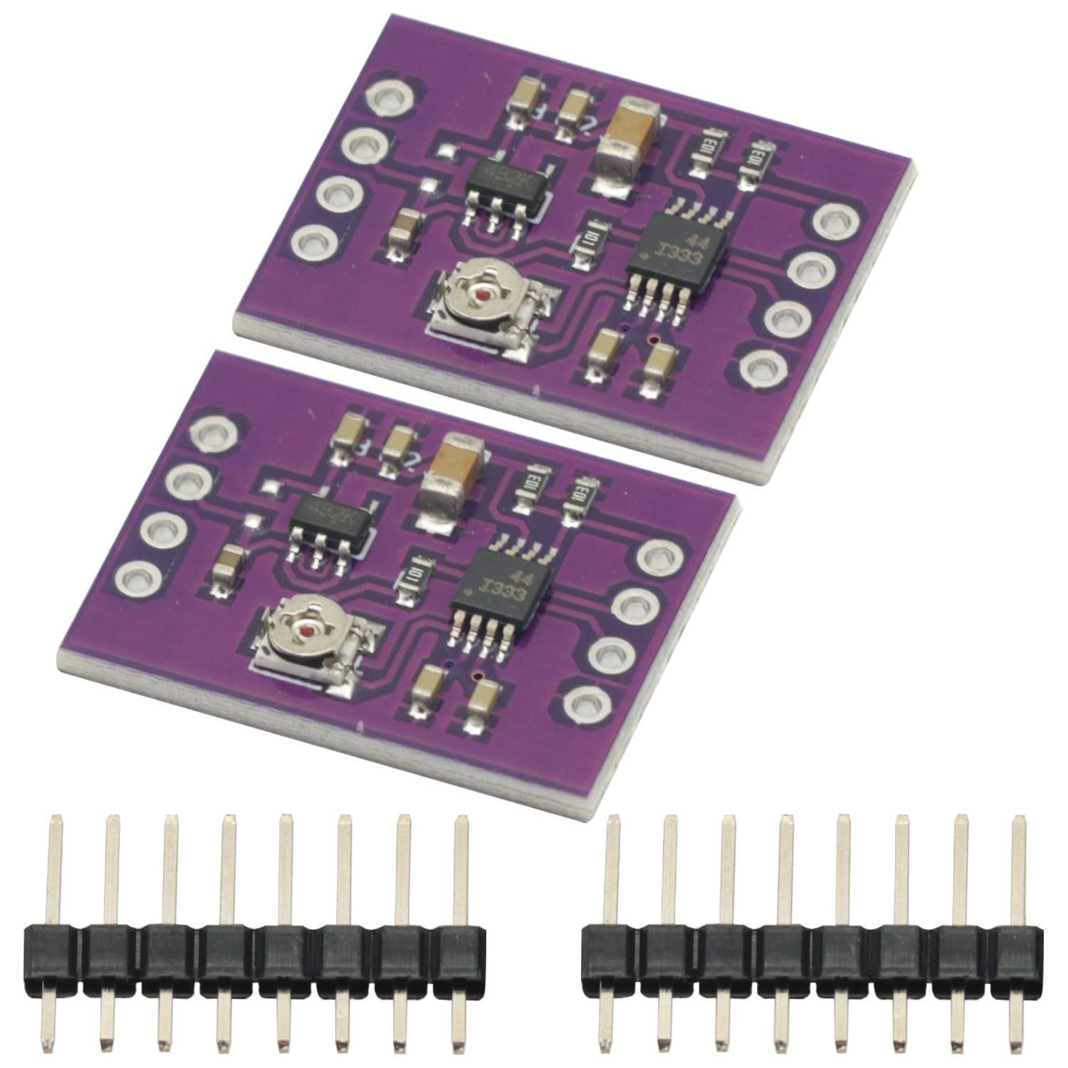
Figure 1: INA333 Low Power Precision Instrumentation Ampko'taruvchi modul.
2. Asosiy xususiyatlar
- Low-power, precision instrumentation amphayotiyroq.
- Past ofset Voltage: 25 µV (Maximum) at G ≥ 100.
- Low Drift: 0.1 µV/°C at G ≥ 100.
- Low Noise: 50 nV/√Hz at G ≥ 100.
- Wide Supply Range: +1.8V to +5.5V.
- Integrated 3 operational ampko'taruvchi dizayni.
3. Qutida nima bor
Sizning paketingiz quyidagi elementlarni o'z ichiga olishi kerak:
- 2 x INA333 Low Power Precision Instrumentation Ampko'taruvchi modullar.
- Associated pin headers for connection.

Figure 2: Two INA333 modules and pin headers included in the package.
4. Texnik spetsifikatsiyalar
| Parametr | Qiymat |
|---|---|
| Model | Mod-INA333-002 |
| Brend | GODIYMODULLAR |
| Amphayot turi | Asboblar Amphayotiyroq |
| Kanallar soni | 3 (Operational Ampko'taruvchilar) |
| Minimal ta'minot hajmitage | 1.8 volt (DC) |
| Maksimal ta'minot hajmitage | 5.5 volt (DC) |
| Past ofset Voltage | 25 µV (Max, G ≥ 100) |
| Low Drift | 0.1 µV/°C (G ≥ 100) |
| Kam shovqin | 50 nV/√Hz (G ≥ 100) |
5. Oʻrnatish va oʻrnatish
This section details the steps for connecting and setting up your INA333 module. Ensure all power is disconnected before making any connections.
5.1 Pinout diagrammasi
The INA333 module features several pins for power, input, output, and reference voltage. Refer to the pinout diagram below for proper identification.

Figure 3: Pinout of the INA333 module. Key pins include VREF, VOUT, 3.3V, GND, VCC, VIN-, and VIN+.
- VCC: Power supply input (+1.8V to +5.5V).
- GND: Yerga ulanish.
- VIN+: Non-inverting input for the differential signal.
- VIN-: Inverting input for the differential signal.
- VO'T: Ampliified chiqish jildtage.
- VREF: Ma'lumotnoma jildtage input for the output. Typically connected to GND for a unipolar output or a specific voltage for bipolar output.
- 3.3V: Onboard 3.3V regulator output (if applicable, check schematic for details).
5.2 Basic Connection Diagram
The following schematic illustrates a typical connection for the INA333 module. This diagram provides a general guide for integrating the module into your circuit.

Figure 4: Basic schematic diagram for the INA333 module, showing power, input, and output connections.
For detailed circuit implementation and gain configuration, refer to the full schematic diagram and the INA333 datasheet from Texas Instruments.

Figure 5: Detailed circuit diagram of the INA333 module, including the TPS73033DBVT regulator and INA333 IC connections.
6. Operatsiya
The INA333 module is designed to amplify small differential signals with high precision. Its operation primarily involves providing power, input signals, and setting the gain.
6.1 Elektr ta'minoti
Connect a stable DC power supply within the range of +1.8V to +5.5V to the VCC va GND pins. Ensure the power supply is clean and free from excessive noise to maintain the amplifier's precision.
6.2 Input Signal Connection
Connect your differential input signal to the VIN+ va VIN- pins. The INA333 is optimized for measuring small voltage differences between these two points, rejecting common-mode noise.
6.3 Chiqish jildtage
The amplified output signal is available at the TAVSISH pin. The output voltage range will depend on the supply voltage va ma'lumotnoma jildtage (VREF).
6.4 Daromadni sozlash
The gain of the INA333 is set by an external resistor, typically labeled RG. The module includes a potentiometer (visible in Figure 6) which allows for adjustable gain. Rotate the potentiometer using a small screwdriver to adjust the amplification factor according to your application's requirements. Refer to the INA333 datasheet for the precise gain formula and resistor values.

6-rasm: Yuqori view of a single INA333 module, highlighting the potentiometer used for gain adjustment.
7. Xizmat ko'rsatish
The INA333 module is a robust electronic component designed for long-term operation with minimal maintenance. Follow these guidelines to ensure its longevity:
- Toza tuting: Avoid dust, dirt, and moisture accumulation on the module. Use a soft, dry brush or compressed air for cleaning if necessary.
- Ehtiyotkorlik bilan ishlang: Electronic components are sensitive to electrostatic discharge (ESD). Handle the module by its edges and use appropriate ESD precautions.
- To'g'ri saqlash: Store the module in a dry, cool environment, away from direct sunlight and extreme temperatures.
- Overvoldan saqlaningtage: Ta'minot hajmini ta'minlangtage and input signals do not exceed the specified maximum ratings to prevent damage.
8. Muammolarni bartaraf qilish; nosozliklarni TUZATISH
If you encounter issues with your INA333 module, consider the following troubleshooting steps:
- No Output/Incorrect Output:
- Verify power supply connections (VCC and GND) and ensure the voltage is within the +1.8V to +5.5V range.
- Check input signal connections (VIN+ and VIN-) for proper polarity and continuity.
- Ensure the VREF pin is correctly connected (e.g., to GND for unipolar output).
- Adjust the gain potentiometer to see if the output changes.
- Excessive Noise in Output:
- Ensure your power supply is stable and filtered.
- Check for proper grounding of the module and your sensor.
- Keep input signal wires short and shielded if possible.
- Verify that the operating environment is free from strong electromagnetic interference.
- Modul yoqilmaydi:
- Double-check all power connections.
- Volumni o'lchangtage at the VCC pin to confirm it is receiving power.
- Inspect the module for any visible damage or short circuits.
Agar bu qadamlar muammoni hal qilmasa, qo'shimcha yordam olish uchun mijozlarni qo'llab-quvvatlash xizmatiga murojaat qiling.
9. Qo'llab-quvvatlash va kafolat
For technical support, product inquiries, or warranty information, please refer to the seller's contact details on the platform where you purchased this product. Keep your purchase receipt or order number handy for faster service.
GODIYMODULES is committed to providing quality electronic components. While specific warranty terms may vary by region and retailer, we strive to ensure customer satisfaction. Please reach out to your point of purchase for detailed warranty policies.